Author Archive

CM5 Update for Jacobian communications structure

February 2, 2012

In way to provide the users with a faster and more stable communication, some improvements have been done in the CM5 firmware.

This includes, communication auto-restart, if the servos communication gets lost, will be automatically restarted in way to get the structure communicating non-stop,

along with the current server loop start. So Every time that servos are added, changed or renumbered, just have to get power down and up again and the system will restart and set back running by it self.


CM5_stable_version


Hope it helps, Enjoy


Jacobian juggernaut

April 6, 2011

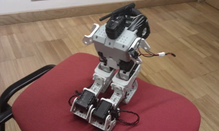
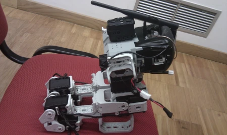
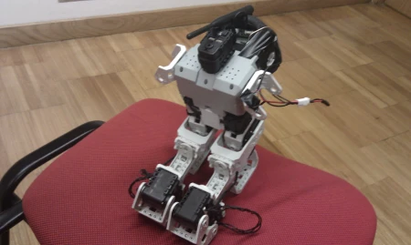
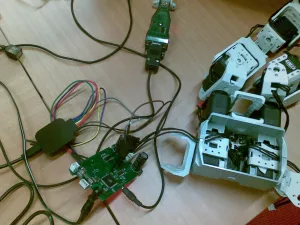
The first juggernaut pics of the assembled Jacobian.

Jacobian Communication infrastructure

April 5, 2011

The Jacobian body communication infrastructure, is devided now in three parts,

– The Servos

– The Cm5 and IMU

– The Linux Sfunction

With these we can provide a constant access to the body, by the Matlab and then control the robot.

We can now have a stable infrastructure working at 200fps, meaning this, we can get data from servos and IMU, and send back new data to servos, 200 times per second.

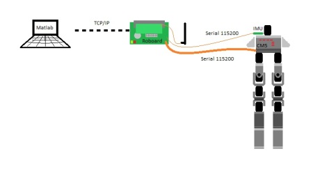
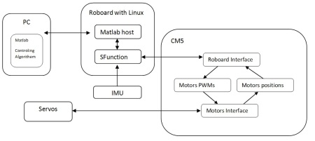
The whole system is composed by

The PC with the Matlab client and control algorithem, communicate with the Roboard

The roboard have a Matlab host code to communicate with PC, and uses an Sfunction to interface the CM5 and the IMU

The IMU broadcast yaw, pitch and roll data at 300Hz

The CM5 reply packets with the servos positions when the roboard request it, and send to servos the new pwm values the roboard send

The CM5 also have a vector with all the servos positions, that is updated every 3 ms.

The servos send their positions in chain reply when CM5 request a cycle of position replies, and each get the new pwm that CM5 send on single broadcasted packet.

The follow example code, is used to access positions and control the PWM of 10 pre configured Servos.

The Servos must be programmed with the morpheus firmware and all of them must have diferent IDs.

The CM5 should have the following code running.

Just them compile and run the linux example from the roboard

Servos Code is in the previous post

CM5 Code.rar

Linux Code.rar

 UPDATE NOTE:

Newer CM5 firmware released in recent post

Installing wireless VT6655 on roboard

February 28, 2011

The installation of the wireless card in the roboard is as in the following 5 steps.

(1)  Getting the needed tools

Beside the packages to the linux, we might use usefull tools like putty, a ssh terminal to access the roboard if you know the IP and WinSCP to access the roboard folders as an easy way to manage and drag and drop files or folders, from windows environment.

Getting the linux tools

Get the bzip2 # apt-get install bzip2

Get the make # apt-get install bzip2

Get the gcc # apt-get install gcc

Get the unrar #apt-get install unrar-free

Get the wireless-tools # apt-get istall wireless-tools

Get the wpa supplicant # apt-get install wpasupplicant

(2) Installing the compatible version of linux

To install the wireless card VT6655 on the roboard we need first do install a linux 2.6.30 version, we can do this by copying the Linux-Image-2.6.30-vortex86mx deb file to the roboard and then install.

After burning the pendrive  instead copying the image 2.6.34.1 version to the root directory of the pendrive, copy the 2.6.30, and follow the rest of the roboard installation.

If your roboard is already installed, just copy the image.deb file to a roboard folder and then, inside the same folder, do

# cd /usr/src

# dpkg -i image.deb

# update-initramfs -k 2.6.30-vortex86mx -c

# update-grub

Reboot the system now and then restart with the 2.6.30 version linux

Use “apt-get remove” to uninstall other version of kernel that might interfere on boot

(3) Copying the needed material to install the card

Download the following link files to you computer and place them on a roboard folder, in our case /usr/src/

config

VT6655-Drivers or Download from VIA site

linux-2.6.30-kernel

(4) Compiling and Installing the 2.6.30 kernel

Decompress the linux 2.6.30 kernel.

# tar -xf linux-2.6.30-vortex86mx.tar.bz2

This might take a long time.

# cd /usr/src/linux-2.6.30

# cp ../config-2.6.30-vortex86mx-apm .config

# make modules_prepare

# rmdir –ignore-fail-on-non-empty /lib/modules/2.6.30-vortex86mx-apm/build

Check if the directory still in there, with the winspc, if it still exists delete it

Now create a link to the folder
# ln -sf /usr/src/linux-2.6.30 /lib/modules/2.6.30-vortex86mx/build


(5) Compiling and Installing the VT6655 driver

# unrar /usr/src/VT6655_Linux_src_v1.20.02_x86.rar

# cd VT6655_Linux_src_v1.20.02_x86/driver

# cp vntconfiguration.dat /etc

# make && make install

Reboot

(5) Testing the card

After booting, look for the card in the boot

# dmesg | grep via

[    6.783647] eth1 (viawget): not using net_device_ops yet

To test the card, for example try just to lookup for avaliable wireless networks, put on terminal

# iwlist ethX scan

Where ethX is your ethernet wireless and the return is looked like
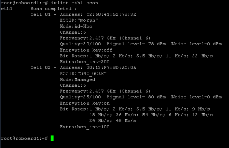
To configure your network we can also give some hints.

Using wpa supplicant method, edit the /etc/network/interfaces file and add another ethernet interface, your wireless interface, for example like this

# This file describes the network interfaces available on your system

# and how to activate them. For more information, see interfaces(5).
# The loopback network interface

auto lo

iface lo inet loopback
# The primary network interface

auto eth0

allow-hotplug eth0

#iface eth0 inet dhcp

iface eth0 inet static

address 192.168.0.252

gateway 192.168.0.1

netmask 255.255.255.0

network 192.168.0.0

brodcast 192.168.0.255

# the wireless interface 1

auto eth1

allow-hotplug eth1

iface eth1 inet dhcp

wpa-conf /usr/src/wpa_supplicant.conf

Where our device is configured as dhcp and the configuration file wpa_supplicant.conf is in the folder /usr/src.

Now you can look at http://linux.die.net/man/5/wpa_supplicant.conf to see how to build your network access configuration file.

Enjoy
Installing Debian on Roboard its now a bit easier!

February 17, 2011

Installing debian on roboard its now a bit easier!


First of all, this process does not replace the total of the steps given in the ROBOARD manual needed to install the linux on the roboard.

This ISO image is just the way to avoid the mess of installing virtual machines on windows and losing time building the pendrive that will be used after, to install the linux on the ROBOARD.

So, we have created these iso images that we are able to “burn” on pendrives and just plug the pendrives on the roboard and boot it!

After this you still have to follow linux instalation steps, after pendrive creation, of the debian installation manual, supplied in the roboard site.

We also recomend to have the roboard connected to internet when installing it, so linux may fetch what else it needs from web.


Its possible to burn the image to a pen, in linux or in windows, ahead follow the instruction.

To build these images, we  have used  the debian 6.0.0 businesscard version.

Burning the image on Windows

1st Download the WindowsImage of the installer pendrive

2nd Download USBit tool

3rd Connect the pendrive to use as roboard installer throught USB with at least +128MB

Unzip the usbit.zip previouse downloaded, and run the USB Image Tool.exe.

Press refress button and select your pendrive on the list of found devices

Click restore and select your windows ISO file previousely downloaded

Click Open and wait for the restoring to finish

Burning the Image on Linux

1st Download the LinuxImage of the installer pendrive

2nd Connect the pendrive to use as roboard installer throught USB with at least +128MB

3rd Open a terminal and insert the code line

$ dd if=DebianImage.iso of=/dev/sdb1

NOTE:
In our case, we are on the same folder as the image is, and the pendrive is the sdb1.


After burning the image to the pendrive,

If you pretend to use the version 2.6.34.1 of the image, unzip the linux_image.rar file now existing in the Pendrive root.

Put the *.deb file contained in the forder created by the unzip, in the pendrive root directory.

Otherwise, if you pretend other versio, since compatible with the vortex, copy the respective image.deb file to the pendrive root directory and forget about the previouse rar file.

Then remove the Pendrive.

Installing…

Insert the pendrive in the roboard USB and Start the Board

Press F11 on while the board is starting to enter the Boot selection

Select your pendrive and continue

Follow Debian installation instructions.

Also you can find  the roboard installation help in www.roboard.com/Files/RB-100/Install_Debian_on_RoBoard.zip after the pendrive building part.

Enjoy!

AX12 Custom Firmware Version 1.2

February 14, 2011

This version of firmware have a similar to bioloid type of control, but have been developed thinking on the new features that allow a much faster closed loop control.

Directly controlling the PWM of the Jacobian 10 servos with the roboard 110.

With this firmware we could reach the 600 fps with 10 servos frames, for pwm control.

The interfacing GUI is a simple example of how to interface the servo.

Any modification, bug report or suggestion is wellcome to be commented.

Firmware and GUI interface Software ( Projects also)

Morpheus Firmware.zip (new version 1.2)

Morpheus GUI.zip

Firmware helper.pdf

GUI helper.pdf

Roboard Linux Code.c

Note:

The new version 1.2 has corrected some bugs in the speed control and in the communication freezing.

Re-flashing AX12 to the Original Dynamixel Firmware

January 20, 2011

For the interested in returning to the original AX-12 firmware after reflashing the servo with a custom made firmware, here are the steps

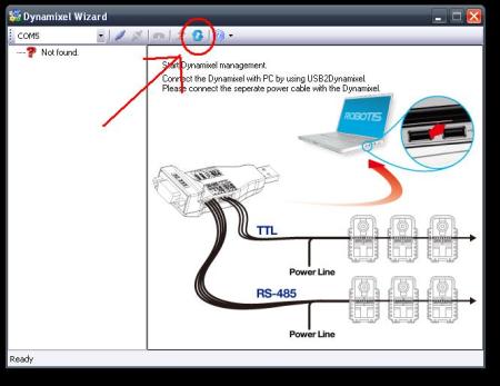
1- Open from Robotis Software the Dynamixel Wizard

2- Make sure that you’re not connected to any serial com

3- Press the button with dual pointing circular arrows “Dynamixel Firmware Recovering”

4- Follow the instructions.

From there you can recover your dynamixel servo and if need just reprogram the parameters.

Custom AX12 Servo Firmware

December 11, 2010

As we need to improve not just the communication speed by changing the communication protocol, but also to adapt the servo data format and the servo data inputs to our control type. We are developing our own AX12 servo firmware so that we can drive the closed loop control from the embedded linux at high speed. Here are a list of objectives:

1) maximize the control loop by having the servos send their position/speed/voltage continously without requiring the Master to request their data.
2) Servos deploy 2 control algorithms. Speed Control when moving between target position ; Position Control once reaching target position

Communication speed and protocol

The first version will have mapping of servos on bus per each servo, with this we can make the servos send the position and speed one after the other without needing to send a data request first.

This mapping is started by the Master ( CM5 or ROBOARD ) which sends an initial “stand up and be counted” packet. Every servo waits until he thinks it is his turn to communicate based on his own servo ID number.

Once they are counted, the master has a map of the servos on the bus and then servos send their data (position, speed, voltage) continuously. Each servo listens to the bus and knows after which servo they must send the data. This is the most efficient way of doing things and should result in the highest theoretical control loop speed at 1mbps baud (depending on number of servos and packet size per servo). The Master has the right to send command packets at the end of a servo-sending-loop.

All the servos do is wait for the previous lower ID servo to send something and he knows it is his turn. Once the last servo sends his packet, it is up to the Master to send a OK packet or to send DATA to one of the servos.

Data format and the servo data inputs

The data packet is similar to robotis packets because we do need a checksum since we have encountered odd noise on the bus. Data to be sent to a servo from the Master:

Postion –  Position from 1 to 0x3FE that represents zero to 300 degrees

Speed   –   The speed is set on 10% steps, meaning from 0 to 100% of the maximum speed we have 10 steps as it is not really possible to control the AX12 speed at higher resolution.

Spring  –  A spring effect is emulated at the target position when external torque is applied to the shaft of the servo. Once the servo reaches target position, it switches from speed control to position control. In position control mode, the further the angle is from the target position, the more power the servo applies to correct the offset. This is a linear increase from 0 to FF representing the deviation angle at which point the Maximum power will be applied. At target position, zero power is applied.

Maximum Power – This maximum power limit goes from 0 to 100% of the total power available from the battery. this value applies for both Speed Control and Position Control modes.

Control example

On this demo we have a cycle that set a goal position of 1022 at a speed of 100% and when reach the position set the next Goal point as 1 at a speed of 10%. Always 100%  maximum power. (Servo has a demo code inside no external control being made)

Source Code

AX12_example.zip

Roboard code examples to interface CM5 Firmware and IMU

December 11, 2010

The following post briefly explains how did we interfaced the roboard and contains the code files that we’ve used.

Roboard and CM5 communication

A detailed explanation to the structure of the CM5 code and the data flux between the servos and the roboard, can be found on the previouse post  Communication protocol between PC and CM5.

The roboard code to interface the CM5 is quite simple,

The IMU interface code its even more easy, we just get the data from the IMU through a serial comm at a baudrate of 115200 (check IMU datasheet) and display the values on the Standard Output.

In attach follow a zip file with 3 codes and a readme document with file list and content of the Zip file.

1) The CM5 code to run on the CM5, the one that makes the bridge between the roboard and the servos.

2) A linux code that run on roboard, that makes the closed loop test to the servos through CM5 ( using code 1)  ) as previously described.

3) A linux code that run on Roboard, that simply collect the data from the IMU and show it on the screen.

Code.zip

CM5 code to interface Roboard and Servos

October 30, 2010

The code to interface the Servos and the Roboard has already been explained on previouse post, so as brief explanation, this code colects the data from the servos, compose a pack with it and send it to the Roboard.
When the Roboard send a packet containing broadcast packets to the servos data, the CM5 will redirect the content to the servos.

Here is the first working version of the CM5 firmware.

See full article for the Code to Interface with the Servos

(more…)

CHR-6dm Attitude and Heading Reference System (IMU)

October 30, 2010

This Inertial Moment Unit (IMU) is a bunch of sensors  that are supposed to tell the robot’s brain the position and orientation of the robot. Typically solid state gyros, accelerometers and magnetometers are used. However, these sensors have varying degree of error, delay and accumulating delay and error. To deal with errors, the naive approach is to use a filter that smooths the signal but that approach creates delay. The textbook way of dealing with these limitations is to use a predictive algorithm that assumes that the measured object has body weight and inertia and in return provides a very low latency clean signal. Kalman Filter is the classic solution but more modern algorithms provide better results.

Instead of dealing with these problems, a recent development in IMU’s has spawned several small boards that integrate several sensors plus a small processor that does all the fancy math and sends out a low latency smooth signal in the form of a bit stream. All we lazy robot developers have to do is read the XYZ and yaw-pitch-roll data off the board’s serial connector.

To get the principal space position the IMU is once placed in  the head of our Jacobian1 robot.

The IMU that we are using is CHR-6dm Attitude and Heading Reference System.

” The CHR-6dm AHRS is a cost-effective
orientation sensor providing yaw, pitch, and
roll angle outputs at up to 300 Hz.  An
Extended Kalman Filter (EKF) combines data
from onboard accelerometers, rate gyros,
and magnetic sensors to produce yaw, pitch,
and roll angle estimates.
Communication with the CHR-6dm is
performed over a           L (3.3V) UART at 115200
Baud.  The AHRS can be configured to
transmit raw sensor in addition to angle estimates, and the transmission rate can be configured
in 1 Hz increments from 20 Hz to 300 Hz.  Alternatively, the CHR-6dm can operate in “silent
mode,” where data is transmitted only when specific requests are received over the UART.
Regardless of the transmission mode and rate, internal angle estimates are maintained at over
500 Hz to ensure long-term accuracy.
The CHR-6dm simplifies integration by providing a number of automatic calibration routines,
including rate gyro bias calibration, magnetometer hard and soft iron calibration, and
accelerometer “zeroing” to compensate for AHRS-platform misalignment.  All calibration routines
are triggered by sending simple commands over the serial interface.

The CHR-6dm AHRS is a cost-effective  orientation sensor providing yaw, pitch, and  roll angle outputs at up to 300 Hz.  An  Extended Kalman Filter (EKF) combines data  from onboard accelerometers, rate gyros,  and magnetic sensors to produce yaw, pitch,  and roll angle estimates.    Communication with the CHR-6dm is  performed over a           L (3.3V) UART at 115200  Baud.  The AHRS can be configured to  transmit raw sensor in addition to angle estimates, and the transmission rate can be configured  in 1 Hz increments from 20 Hz to 300 Hz.  Alternatively, the CHR-6dm can operate in “silent  mode,” where data is transmitted only when specific requests are received over the UART.   Regardless of the transmission mode and rate, internal angle estimates are maintained at over  500 Hz to ensure long-term accuracy.    The CHR-6dm simplifies integration by providing a number of automatic calibration routines,  including rate gyro bias calibration, magnetometer hard and soft iron calibration, and  accelerometer “zeroing” to compensate for AHRS-platform misalignment.  All calibration routines  are triggered by sending simple commands over the serial interface. …”

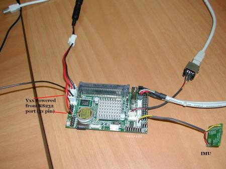
To test the IMU, we are using a RB110 Roboard and one of the first problems that we had, was that UART 3 and 4 were not found by Linux, so as temporary work around, we just disabled UART 0 and 1 in the BIOS and put the same IRQ interruption address of  0 and 1 , to 3 and 4.

To connect the IMU to the board, we have used the 5v from UART0 to supply the Vxx (see RB110 datasheet page 8 to 14) for the experience, once the power available on the Uart3 pins is Vxx.

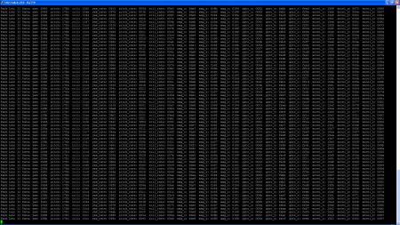
On our first test, with Roboard and the IMU, is a little code running in the Roboard that unpack the data from IMU and just print it, with 115200 Baud of speed in UART3.

Testing and evaluating Servos performance

October 27, 2010

(22-10-2010)

With the CM5 firmware ready, its now time to make a little program on the roboard, to test the servos.

This program will test the delay that the servos take moving between several angles, for example between 0º and 300º, or 0º to 100º, etc.

We will also run these tests on the  same servos, in several conditions, with different loads, different supply voltages, different maximum torques, and both at the same time.

We will also test the torques with different voltages .

The idea is to profile the servos as best we can so that they can accurately be emulated in EZPysics.

(27-10-2010)

At this point, we wrote a little program that sends the servos to a start point, and then to an end point, and repeats the process for 10 times.

During this process, the program saves to a file, every servomotor positions and make a timestamp with uSeconds precision, each time it receives a new packet from Roboard containing the servos data.

We reached the following results so far:

1) With 10 servos we get and average of 283 packets per second coming from the CM5

2) Some servos are slower than others.

3) around 1 second to go from 0 to 1023 which means 300º/sec at 12V in accordance with AX12 specs

4) the worst delay between any two servos was around 21º for completion of the 300º. This translates to around 7% error.

5) The old AX12 servos seem to be more problematic and some of the physical connectors seem to be faulty maybe due to so much messing around.

After this we just took the file from the roboard, using winscp, and imported it to Exel, elaborating a graphic, to easily visualize, the behaviour of the servos in time.

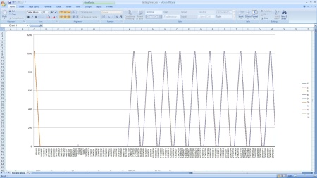
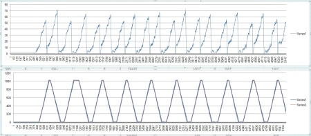
In the picture below you can see that some AX12 servos are faster than others. The servos are told to move from position 0 to position 1023 and then back. During the transition, the CM5 continuously captures the servo positions (at around 280 times per second) and sends those positions to the RoBoard, which in turn stores them in CSV file format which Excel then transforms into nice graphs.

The top graph shows the difference between the maximum and minimum values among the 10 servos sampled at 280/sec. The bottom graph shows the absolute positions of the fastest and slowest servo.

As you can see, the RoBoard waits for all the servos to reach 0 before sending them off to 1023, then waiting for all of them to reach that position and so on.

See the full article to view the C code running on the RoBoard Linux

(more…)

Problems with the communication, due to physical RS232 interface limitations

September 24, 2010
Our goal to have 1mbps communication between the CM5 and the Roboard, this is necessary to get as much as possible free processor time between packets.
The PC communications link on both the CM5 and CM510 is based on RS232 standard (12V).
The AVR processor on these boards has serial UART ports at 5V standard (TTL/CMOS). To do the step-up voltage conversion, CM5 uses the HIN232 chip and CM510 uses the MAX202C chip. Unfortunately these chips can only drive 125kbps and not 1mbps as we need.
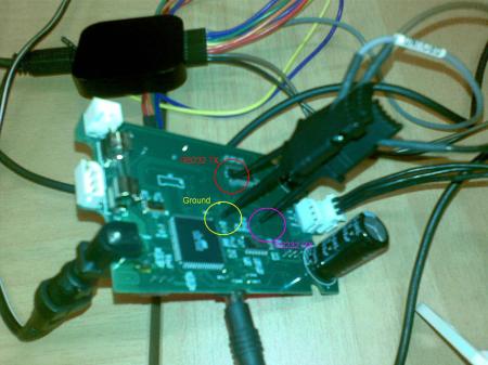
To analyze the RS232 communications we have used the Saleae Logic Analyzer, connected to the lines between the Atmega microcontroller and the RS232 Transceiver (HIN232). You can see the probes in the following picture.
Our Communication consists in a packet from CM5 to Roboard composed by
[0xFF] [0xFF] [Len] [ID1] [POSLsb] [POSMsb] [ID2] [POSLsb][POSMsb]…[IDn] [POSLsb] [POSMsb] [CRC]
In reply to this packet Roboard has to send another packet that is basicly a an emcapsulation of Servo Sync write packets inside a single packet, composed by
[0xFA] [0xFA] [PacketLenLsb] [PacketLenMsb] [Sync write Packet 1] [Sync write Packet 2] … [Sync write Packet N] [CRC]
and a Servo Sync write Packet Packet is composed by
[0xFF] [0xFF] [0xFE][Len][0x83][ServoStartAddress][NbytesToRight][ID1] [Data1] [Data2] […] [DataN] [ID2] [Data1] [Data2] […] [DataN]…[IDn] [Data1] [Data2] […] [DataN][CRC]

In this case we just have one servo broadcast packet to send, to set positions on servos.
Even though the chips are rated with 125Kbps limitation, we manage to get stable communication at 500Kbps but only in one direction : CM5 to PC. In the picture below you can see the sequence of bytes sent from the CM5 to the Roboard and perfectly captured.

In the picture below you can see that the sequence of bytes sent between the  PC and the CM5, data flowing both directions at 500kbps, one communication and reply goes well but the second is not received correctly.

Analyzing a the packet we can see the difference between the bytes that we want to send the CM5, and the bytes being actually sent on the wire.


If the CM5-Roboard speed becomes a bottleneck, we will replace the the CM5 and the CM510 IC components with a chip called TRSF3232E from Texas Instruments that has the exact same package and pinout but supports 1Mb/s speed, this change may also require changing the capacitors used as “voltage pumps” in accordance with TRSF3232E component datasheet.

Installing Linux on Roboard and FTDI tests

September 19, 2010

Installing ROBOARD with linux-image-2.6.29.1-vortex86dx

In the ROBOARD page we found what we need to do the installation following the regular Tutorial of installation of Debian Lenny. We also have in the drivers and the board RB100 manual and RB110 manual.

Everything went well until the installation blocks on the Ethernet devices search.

To solve it, the solution was setting the USB DEVICE on the BIOS, as “Force FDD”.

To Install the Debian on it, we need ethernet connection, which brougth us another problem, the roboard RB110, the one with the FTDI chip, had a problem of non recognized MAC ADDRESS by the bios, to solve this, we’ve used MAC_Tools given by roboard Tech help.

After a successful installation, we needed to install the FTDI drivers to control the chip, install GCC and G++, and editor, in this case, FTE and vim had to be installed using apt-get.

Installing a d2xx driver was simple, just need to follow the instructions on www.ftdichip.com, and it will recognize the chip and use the driver. We didn’t use the on-board chip but rather used an external device (USB2Dynamixel from Robotis) in order to connect the RoBoard to the CM5 Bioloid controller via its UART1.

CM5 UART -> RS232 level converting chip -> USB2Dynamixel -> USB -> RoBoard.

Installing the VCP (Virtual serial Communications Port) driver, was not so easy, the compilation had a lot of errors, found that there was a mismatch of kernel and lib symbolic links, and a lot of other problems, so we did not manage to get it working. The VCP driver for Linux was written by some guy on sourceforge and not formally endorsed by FTDI.

To solve this problem we decided to install ROBOARD with linux-image-2.6.34.1-vortex86dx, already released, it comes with the FTDI chip VCP drivers, which is automatically recognized on the system, and ready to use, even with hot plug.

A Little program have been made to test the ttyUSB port, based on a loop.

Example code:

#include <sys/time.h>
#include <sys/types.h>
#include <unistd.h>
#include <stdio.h>
#include <sys/types.h>
#include <sys/stat.h>
#include <fcntl.h>
#include <termios.h>
int main(void)
{
    fd_set Reading;
    int fdHandler;
    struct timeval timeout;
    char Data;
    struct termios termios_p;
    fdHandler = open(“/dev/ttyUSB0?,O_NONBLOCK|O_RDWR|O_NOCTTY);
    if(fdHandler==-1)
    {
        //shit hapened
        puts(“Error Opening”);
    }
    puts(“Port Open\n\rApply Settings”);
    termios_p.c_iflag=0/*IGNPAR | ICRNL*/;
    termios_p.c_oflag=0;
    termios_p.c_cflag= B500000/*|CRTSCTS*/|CREAD|CS8|CLOCAL;
    termios_p.c_lflag=0;
    termios_p.c_cc[VINTR]    = 0;     /* Ctrl-c */
    termios_p.c_cc[VQUIT]    = 0;     /* Ctrl-\ */
    termios_p.c_cc[VERASE]   = 0;     /* del */
    termios_p.c_cc[VKILL]    = 0;     /* @ */
    termios_p.c_cc[VEOF]     = 0;     /* Ctrl-d */
    termios_p.c_cc[VTIME]    = 0;     /* inter-character timer unused */
    termios_p.c_cc[VMIN]     = 0;     /* blocking read until 1 character arrives */
    termios_p.c_cc[VSWTC]    = 0;     /* ” */
    termios_p.c_cc[VSTART]   = 0;     /* Ctrl-q */
    termios_p.c_cc[VSTOP]    = 0;     /* Ctrl-s */
    termios_p.c_cc[VSUSP]    = 0;     /* Ctrl-z */
    termios_p.c_cc[VEOL]     = 0;     /* ” */
    termios_p.c_cc[VREPRINT] = 0;     /* Ctrl-r */
    termios_p.c_cc[VDISCARD] = 0;     /* Ctrl-u */
    termios_p.c_cc[VWERASE]  = 0;     /* Ctrl-w */
    termios_p.c_cc[VLNEXT]   = 0;     /* Ctrl-v */
    termios_p.c_cc[VEOL2]    = 0;     /* ” */
    tcflush(fdHandler, TCIFLUSH);
    if(tcsetattr(fdHandler,TCSANOW, &termios_p)==-1)
    {
        puts(“Error setting configurations”);
        return 0;
    }
    FD_ZERO(&Reading);
    while(1)
    {
        timeout.tv_sec  = 1;
        timeout.tv_usec = 0;
        FD_SET(fdHandler,&Reading);
        puts(“Send: A”);
        write(fdHandler,”A”,1);
        if(select(100,&Reading, NULL, NULL, &timeout)==-1)
        {
            puts(“Select Fail”);
        }
        if(FD_ISSET(fdHandler,&Reading))
        {
            puts(“Received: “);
            read(fdHandler,&Data,1);
            puts(&Data);
        }
    }
}
Code to html converted using CodeHTMLer

Communication protocol between PC and CM5

August 2, 2010

The communication is based on the need of controlling the servos position, speed and torque according to the  mathematical algorithms, in this case we need servos position, speed and load as inputs to the algorithms and the outputs will be new servos positions and torque.

To do this communication between the servos and the PC efficient and fast, is used the CM5 as intermediate.

The CM5 has a firmware that keeps running in loop refreshing the servos data, checking PC new incoming data to servos and retrieving the new servo data to be sent to PC, each cycle.

To do this, CM5 have three stages since it boots up. (more…)