Placement of IMU

June 12, 2012 by

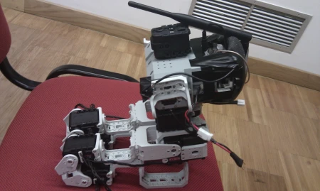
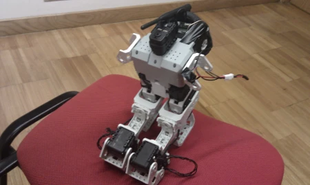
In order to proceed with our work it was needed to find the hidden problems in this system, and for that the easiest approach is to simplify the structure.

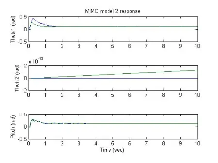
After some experimentation we found that because we are using the kalman estimator from the IMU we were getting “false data”.  The kalman estimator has a slow stabilization, and only when it is stable the data it send is reliable.

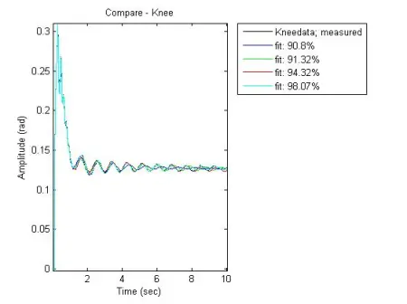
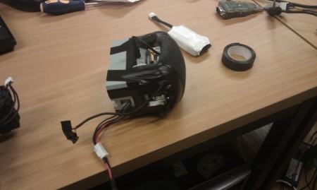
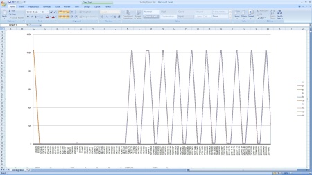
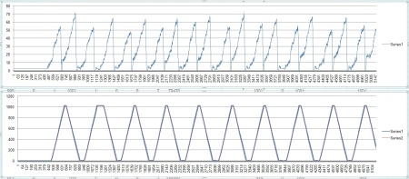
Because we were applying fast transitions in order to identify the robot we were getting data that was not reliable. By simply changing the location of the IMU we can get the reliable data expected. You can see the comparison between results here.

Another solution is looking at raw data, like gyro data, instead of estimated data.


CM5 Update for Jacobian communications structure

February 2, 2012 by

In way to provide the users with a faster and more stable communication, some improvements have been done in the CM5 firmware.

This includes, communication auto-restart, if the servos communication gets lost, will be automatically restarted in way to get the structure communicating non-stop,

along with the current server loop start. So Every time that servos are added, changed or renumbered, just have to get power down and up again and the system will restart and set back running by it self.


CM5_stable_version


Hope it helps, Enjoy


Controller Performance

September 25, 2011 by

The controller for the suspended pendulum is finally showing good results.

In the video bellow you can see two robots, they are exactly the same, but the one in front is actuated with a LQR controller, while the one behind does not have any kind of control action.

As you can see the one with a controller stabilizes faster than the one without it. We are still optimizing this controller to be faster, because when the robot is inverted it is needed that the control action is faster than what  currently is, otherwise the robot will fall.

Dead-zone of servos

August 29, 2011 by

Linear controllers do not deal well with non linearities like dead-zones of servos, and LQR is not an exception.

Currently we are working in a way to go arround it in order to obtain better results, and avoiding having problems when the controller for keeping it standing is designed.

An explanation of the “tricks” used and the graphical results can be viewed here.

More interesting than theory is actually seeing the effects of the “tricks” in the real robot, therefore we provide you a video with the experiments where the data from the pdf file was taken.

MIMO model assembly

August 23, 2011 by

In the previous post, it was shown the results of identification of the SISO models of the suspended robot.

In this post it is shown how to assemble SISO models into MIMO model, and the results obtained for our project.

The results are still for the suspended robot. It is still needed to invert this model in term of dynamics for us to be able to create a controler to make it stand.

You can find a simple and quick explanation of the process here. This works not only for our case but for all assemblies of SISO models into MIMO models. A precaution to have is to ensure that your project can be described by a set of SISO models.

To finish this post i provide a low quality sample of what you can find in the document.

Jacobian SISO Models

August 8, 2011 by

In order to make the robot to stand it is needed that we know the dynamics from the knee servos to the IMU and from the hip servos to the IMU. These dynamics are being identified based on transfer functions. Even though looking at the behaviour of the structure it is possible to see that what we want is a small order transfer function, the truth is we are dealing with a real signal. This signal has noise and it even measures vibration caused by the high flexibility of the legs of the robot.

Because of these facts the aproach mentioned in previous posts that suggests identifying with greater order models and then simplifying them is used. In the zip file SISO.zip there are pictures of the models identified (original and simplified), and a .txt file saying the orders of the best models (original ones only).

Just a reminder, identification of the transfer functions is done using ArX where the three parameters na, nb and nk represent the order of the denominator, numerator and number of delays, repectively.

Now we procede in assembling these SISO models into a MIMO model that represents the full robot, and from that MIMO model the controler will be synthesized.

I leave you with an example of what you will find in the zip file.

Frequency Identification

August 1, 2011 by

Hello and welcome to the Actuatedcharacter’s blog.

If you have been following us, you know that we are in the process of identifying Jacobian. For that we were using ArX models but the results we were obtaining weren’t that great. It was then suggested for us to try identification in frequency instead of identification in time. The following video shows an experiment to obtain data for frequency identification.

What happens here is that we actuate the knee servos with a sinusoidal signal wich increases the frequency over time, more precisely 0.2 Hz every 10 seconds.

Something unexpected ocurred as we were increasing the frequency. We reached a lateral vibration mode that can clearly be seen on the video.

Meanwhile ArX models are finally showing some decent results and so we went back to them, but it is still an interesting video for those of you who study structural behaviour.

Stay tuned for more updates on the project.

EZPhysics Model Identification

May 13, 2011 by

Following the methodology addressed in the last post to identify the dynamic in order to stabilize the humanoid like a triple inverted pendulum, we performed a new approach based in an identification (ARX model) with a greater order and a truncation to the desired order.

The results were very good, and its dynamic responses virtually identical to EZPhysics responses. See the detailed methodology and results here.

The follow steps is tune an LQR in the identified model to then apply it to model EPZhysics.

Model Identification

April 19, 2011 by

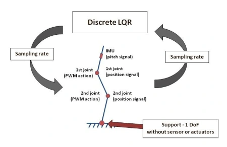
The first step to control the humanoid motion its own stabilization. To perform this stabilization, we pretend to implement a discrete LQR (Linear Quadratic Regulator), which implement a gain matrix in a control close loop. The control system will operate at a sampling rate that is limited by the frequency of communication between the controller (PC / matlab) and robot (real or virtual). In the first approach, we consider that the contact point between the feet and the floor is a rotational joint without sensors or actuators. Thus, the point of contact with the ground only has 1 DoF, to control the stability of the robot is required only the pitch signal from the IMU.

Applied Methodology:
In our approach we will identify the model like a 3 link suspended pendulum to achieved the dynamic of the real model (3 link inverted pendulum) rotating the poles (characteristic of the dynamic system). After to obtain the dynamic of the 3 link inverted pendulum, should be possible to implement a LQR to stabilise the system.

For more detailed information about the methodology to implement the LQR in a 3 link inverted pendulum from the suspended model, see the report here.

Simulations and results:
The simulations was implemented with a frame rate of 200Hz (0.005s).

In our approach we try to obtain the model through the MatLab Identification Toolbox (we use an ARX model) and with the classic dynamic rules.

The detailed information about the obtain data, the methods and first obtain models for the real robot and the EZPhisics, see the report here.

Implementation of a LQR in a 3 inverted pendulum (simulink model))

April 19, 2011 by

To implement the humanoid motion, the first step that need to achieved is its stabilization.
Stabilization is to keep quiet in a humanoid in a certain position.
In first approach, we will considerer that robot has the two legs parallels and the foot connect with the floor with 1DoF.
Thus, the control stabilization of the jacobian is similar like the stabilization of a 3 inverted pendulum under-actuated.
Before the tests with the real or the EZphisics model we perform the first tests with a MatLab/Simulink model, build with the SimMechanics blocks.
For detailed information about the construction of the 3 inverted link model and the implementations of the LQR in MatLab/Simulink see the report here.

Simulations results (continuous LQR):
We performed simulations of the system under vertical stabilization, corresponding to a period of 5 seconds. To analyze the robustness of the LQR we implemented an abrupt perturbation of 1N.m in the torque (along 1 second) of the 2nd actuator in t=1s.

Results for the follow  Ricatti equation parameters:
– Q = 0.1xI6
– R = 1xI2

Results for the follow  Ricatti equation parameters:
– Q = 10xI6
– R = 1xI2

Simulations results (discrete LQR):
Considering that the humanoid will be controlled through a PC with a sampling rate of 100Hz, it is necessary to design a digital controller for this condition.

To analyze the robustness of the LQR we implemented an abrupt perturbation of 0.25N.m in the torque (along 0.2 second) of the 2nd actuator in t=1s.

Results for the follow  Ricatti equation parameters:
– Q = 10xI6
– R = 1xI2

Jacobian juggernaut

April 6, 2011 by

The first juggernaut pics of the assembled Jacobian.

Jacobian Communication infrastructure

April 5, 2011 by

The Jacobian body communication infrastructure, is devided now in three parts,

– The Servos

– The Cm5 and IMU

– The Linux Sfunction

With these we can provide a constant access to the body, by the Matlab and then control the robot.

We can now have a stable infrastructure working at 200fps, meaning this, we can get data from servos and IMU, and send back new data to servos, 200 times per second.

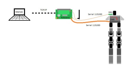
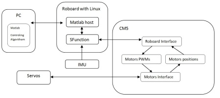
The whole system is composed by

The PC with the Matlab client and control algorithem, communicate with the Roboard

The roboard have a Matlab host code to communicate with PC, and uses an Sfunction to interface the CM5 and the IMU

The IMU broadcast yaw, pitch and roll data at 300Hz

The CM5 reply packets with the servos positions when the roboard request it, and send to servos the new pwm values the roboard send

The CM5 also have a vector with all the servos positions, that is updated every 3 ms.

The servos send their positions in chain reply when CM5 request a cycle of position replies, and each get the new pwm that CM5 send on single broadcasted packet.

The follow example code, is used to access positions and control the PWM of 10 pre configured Servos.

The Servos must be programmed with the morpheus firmware and all of them must have diferent IDs.

The CM5 should have the following code running.

Just them compile and run the linux example from the roboard

Servos Code is in the previous post

CM5 Code.rar

Linux Code.rar

 UPDATE NOTE:

Newer CM5 firmware released in recent post

Installing wireless VT6655 on roboard

February 28, 2011 by

The installation of the wireless card in the roboard is as in the following 5 steps.

(1)  Getting the needed tools

Beside the packages to the linux, we might use usefull tools like putty, a ssh terminal to access the roboard if you know the IP and WinSCP to access the roboard folders as an easy way to manage and drag and drop files or folders, from windows environment.

Getting the linux tools

Get the bzip2 # apt-get install bzip2

Get the make # apt-get install bzip2

Get the gcc # apt-get install gcc

Get the unrar #apt-get install unrar-free

Get the wireless-tools # apt-get istall wireless-tools

Get the wpa supplicant # apt-get install wpasupplicant

(2) Installing the compatible version of linux

To install the wireless card VT6655 on the roboard we need first do install a linux 2.6.30 version, we can do this by copying the Linux-Image-2.6.30-vortex86mx deb file to the roboard and then install.

After burning the pendrive  instead copying the image 2.6.34.1 version to the root directory of the pendrive, copy the 2.6.30, and follow the rest of the roboard installation.

If your roboard is already installed, just copy the image.deb file to a roboard folder and then, inside the same folder, do

# cd /usr/src

# dpkg -i image.deb

# update-initramfs -k 2.6.30-vortex86mx -c

# update-grub

Reboot the system now and then restart with the 2.6.30 version linux

Use “apt-get remove” to uninstall other version of kernel that might interfere on boot

(3) Copying the needed material to install the card

Download the following link files to you computer and place them on a roboard folder, in our case /usr/src/

config

VT6655-Drivers or Download from VIA site

linux-2.6.30-kernel

(4) Compiling and Installing the 2.6.30 kernel

Decompress the linux 2.6.30 kernel.

# tar -xf linux-2.6.30-vortex86mx.tar.bz2

This might take a long time.

# cd /usr/src/linux-2.6.30

# cp ../config-2.6.30-vortex86mx-apm .config

# make modules_prepare

# rmdir –ignore-fail-on-non-empty /lib/modules/2.6.30-vortex86mx-apm/build

Check if the directory still in there, with the winspc, if it still exists delete it

Now create a link to the folder
# ln -sf /usr/src/linux-2.6.30 /lib/modules/2.6.30-vortex86mx/build


(5) Compiling and Installing the VT6655 driver

# unrar /usr/src/VT6655_Linux_src_v1.20.02_x86.rar

# cd VT6655_Linux_src_v1.20.02_x86/driver

# cp vntconfiguration.dat /etc

# make && make install

Reboot

(5) Testing the card

After booting, look for the card in the boot

# dmesg | grep via

[    6.783647] eth1 (viawget): not using net_device_ops yet

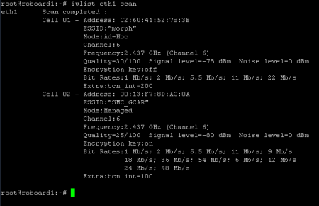
To test the card, for example try just to lookup for avaliable wireless networks, put on terminal

# iwlist ethX scan

Where ethX is your ethernet wireless and the return is looked like
To configure your network we can also give some hints.

Using wpa supplicant method, edit the /etc/network/interfaces file and add another ethernet interface, your wireless interface, for example like this

# This file describes the network interfaces available on your system

# and how to activate them. For more information, see interfaces(5).
# The loopback network interface

auto lo

iface lo inet loopback
# The primary network interface

auto eth0

allow-hotplug eth0

#iface eth0 inet dhcp

iface eth0 inet static

address 192.168.0.252

gateway 192.168.0.1

netmask 255.255.255.0

network 192.168.0.0

brodcast 192.168.0.255

# the wireless interface 1

auto eth1

allow-hotplug eth1

iface eth1 inet dhcp

wpa-conf /usr/src/wpa_supplicant.conf

Where our device is configured as dhcp and the configuration file wpa_supplicant.conf is in the folder /usr/src.

Now you can look at http://linux.die.net/man/5/wpa_supplicant.conf to see how to build your network access configuration file.

Enjoy
Debian Lenny Roboard interaction with Windows Matlab 2010b

February 20, 2011 by

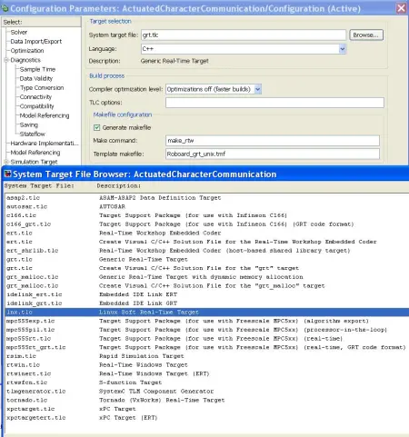
Matlab 2010b’s Simulink as a component that allows for insertion of custom code blocks, code generation and allows building real-time applications with Real-Time Workshop (RTW) (http://www.mathworks.com/help/toolbox/rtw/ug/f1133672.html).

This Matlab component is essential for generating code to run on Unix/Linux systems. This tool has lots of customization options and uses, the most relevant of which is the deployment of a Simulink model to an external device and also the External Mode feature that allows for in Simulink to activate and receive logs and stats feedback from the controler running on the remote device.

There are several examples on how to export/compile code for devices supported by Matlab, however we had to look a bit deeper to code generation feature to parameterize it to the right format in order to compile for Roboard Linux. The most important resource in this endeavor was the previous work developed by Dan Bhanderi (http://bhanderi.dk/downloads/) which made a customized soft real-time Linux target, this was updated last for Matlab 2006b hence it required some tunning to be used in 2010b.

Dan Bhanderi adds a System Target to the RTW options menu that opens new options in the interface and when asked to generate code it does so with a makefile for Unix and the lnx_main.c develop by himself to provide the soft real-time solution. This process of creating a new target uses mainly the Target Language Compiler (TLC) and the Template MakeFile (TMF) files that determine the options in the menus and the format of the makefile respectively. If you want to learn more about it I recommend this pdf (http://www.mathworks.com/support/solutions/attachment.html?resid=1-CAFIKO&solution=1-BHU00D) which is taken from Matlab’s website (http://www.mathworks.com/support/solutions/en/data/1-BHU00D/index.html?solution=1-BHU00D), although a bit off-topic I found it very clear and alot easier to read than the main user guides provided.

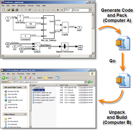
Dan Bhanderi’s instructions are somewhat outdated, so instead of following this steps exactly we found an utility that upon generating code for a model saves all of it’s code and dependencies to a zip file, the packNGo utility. This utility is very useful to discover the necessary source files to run Simulink engine in the current Matlab instalation be it 2010b or any other. In this way, you always know the smallest amount of code needed to run your code on the device. i.e.: set_param(bdroot, ‘PostCodeGenCommand’, ‘packNGo(buildInfo, {”packType” ”hierarchical” ”fileName” ”BioloidControl”});’); (http://blogs.mathworks.com/seth/2008/11/26/wheres-the-code/)

Since we are not using Dan Bhanderi’s TLC or TMF (just using the generic real-time target) we now need to update the makefile and the main to work in the Unix environment. this process involves updating the makefile with the correct filepaths, included libraries (from code used in possible the s-functions in the model), host and make command, and updating the main file with Bhanderi’s soft real-time code (that uses the POSIX timer).

Warning: When transferring files from other operating systems to Unix be careful to update the newline symbols accordingly. (google dos2unix)

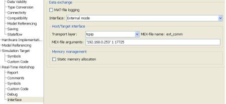
After this process we have the Simulink running on the Roboard, however we whant to see what is happening so we need to activate the External Mode. To do this you access the RTW options under Interface and select External Mode instead of None in the data exchance group. In the mex-file arguments you need to supply the target’s location (so Matlab knows where to get the data) (http://www.mathworks.com/help/techdoc/matlab_external/bp_kqh7.html)

Now if you run the executable in the device with the “-w” parameter it will wait for a connection from Matlab/simulink, upon doing so it will update the scopes data with the values present in your device  (you might have to adjust some settings under the menu Tools->External Mode Control Panel).

Installing Debian on Roboard its now a bit easier!

February 17, 2011 by

Installing debian on roboard its now a bit easier!


First of all, this process does not replace the total of the steps given in the ROBOARD manual needed to install the linux on the roboard.

This ISO image is just the way to avoid the mess of installing virtual machines on windows and losing time building the pendrive that will be used after, to install the linux on the ROBOARD.

So, we have created these iso images that we are able to “burn” on pendrives and just plug the pendrives on the roboard and boot it!

After this you still have to follow linux instalation steps, after pendrive creation, of the debian installation manual, supplied in the roboard site.

We also recomend to have the roboard connected to internet when installing it, so linux may fetch what else it needs from web.


Its possible to burn the image to a pen, in linux or in windows, ahead follow the instruction.

To build these images, we  have used  the debian 6.0.0 businesscard version.

Burning the image on Windows

1st Download the WindowsImage of the installer pendrive

2nd Download USBit tool

3rd Connect the pendrive to use as roboard installer throught USB with at least +128MB

Unzip the usbit.zip previouse downloaded, and run the USB Image Tool.exe.

Press refress button and select your pendrive on the list of found devices

Click restore and select your windows ISO file previousely downloaded

Click Open and wait for the restoring to finish

Burning the Image on Linux

1st Download the LinuxImage of the installer pendrive

2nd Connect the pendrive to use as roboard installer throught USB with at least +128MB

3rd Open a terminal and insert the code line

$ dd if=DebianImage.iso of=/dev/sdb1

NOTE:
In our case, we are on the same folder as the image is, and the pendrive is the sdb1.


After burning the image to the pendrive,

If you pretend to use the version 2.6.34.1 of the image, unzip the linux_image.rar file now existing in the Pendrive root.

Put the *.deb file contained in the forder created by the unzip, in the pendrive root directory.

Otherwise, if you pretend other versio, since compatible with the vortex, copy the respective image.deb file to the pendrive root directory and forget about the previouse rar file.

Then remove the Pendrive.

Installing…

Insert the pendrive in the roboard USB and Start the Board

Press F11 on while the board is starting to enter the Boot selection

Select your pendrive and continue

Follow Debian installation instructions.

Also you can find  the roboard installation help in www.roboard.com/Files/RB-100/Install_Debian_on_RoBoard.zip after the pendrive building part.

Enjoy!

AX12 Custom Firmware Version 1.2

February 14, 2011 by

This version of firmware have a similar to bioloid type of control, but have been developed thinking on the new features that allow a much faster closed loop control.

Directly controlling the PWM of the Jacobian 10 servos with the roboard 110.

With this firmware we could reach the 600 fps with 10 servos frames, for pwm control.

The interfacing GUI is a simple example of how to interface the servo.

Any modification, bug report or suggestion is wellcome to be commented.

Firmware and GUI interface Software ( Projects also)

Morpheus Firmware.zip (new version 1.2)

Morpheus GUI.zip

Firmware helper.pdf

GUI helper.pdf

Roboard Linux Code.c

Note:

The new version 1.2 has corrected some bugs in the speed control and in the communication freezing.

Re-flashing AX12 to the Original Dynamixel Firmware

January 20, 2011 by

For the interested in returning to the original AX-12 firmware after reflashing the servo with a custom made firmware, here are the steps

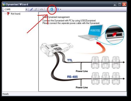
1- Open from Robotis Software the Dynamixel Wizard

2- Make sure that you’re not connected to any serial com

3- Press the button with dual pointing circular arrows “Dynamixel Firmware Recovering”

4- Follow the instructions.

From there you can recover your dynamixel servo and if need just reprogram the parameters.

Custom AX12 Servo Firmware

December 11, 2010 by

As we need to improve not just the communication speed by changing the communication protocol, but also to adapt the servo data format and the servo data inputs to our control type. We are developing our own AX12 servo firmware so that we can drive the closed loop control from the embedded linux at high speed. Here are a list of objectives:

1) maximize the control loop by having the servos send their position/speed/voltage continously without requiring the Master to request their data.
2) Servos deploy 2 control algorithms. Speed Control when moving between target position ; Position Control once reaching target position

Communication speed and protocol

The first version will have mapping of servos on bus per each servo, with this we can make the servos send the position and speed one after the other without needing to send a data request first.

This mapping is started by the Master ( CM5 or ROBOARD ) which sends an initial “stand up and be counted” packet. Every servo waits until he thinks it is his turn to communicate based on his own servo ID number.

Once they are counted, the master has a map of the servos on the bus and then servos send their data (position, speed, voltage) continuously. Each servo listens to the bus and knows after which servo they must send the data. This is the most efficient way of doing things and should result in the highest theoretical control loop speed at 1mbps baud (depending on number of servos and packet size per servo). The Master has the right to send command packets at the end of a servo-sending-loop.

All the servos do is wait for the previous lower ID servo to send something and he knows it is his turn. Once the last servo sends his packet, it is up to the Master to send a OK packet or to send DATA to one of the servos.

Data format and the servo data inputs

The data packet is similar to robotis packets because we do need a checksum since we have encountered odd noise on the bus. Data to be sent to a servo from the Master:

Postion –  Position from 1 to 0x3FE that represents zero to 300 degrees

Speed   –   The speed is set on 10% steps, meaning from 0 to 100% of the maximum speed we have 10 steps as it is not really possible to control the AX12 speed at higher resolution.

Spring  –  A spring effect is emulated at the target position when external torque is applied to the shaft of the servo. Once the servo reaches target position, it switches from speed control to position control. In position control mode, the further the angle is from the target position, the more power the servo applies to correct the offset. This is a linear increase from 0 to FF representing the deviation angle at which point the Maximum power will be applied. At target position, zero power is applied.

Maximum Power – This maximum power limit goes from 0 to 100% of the total power available from the battery. this value applies for both Speed Control and Position Control modes.

Control example

On this demo we have a cycle that set a goal position of 1022 at a speed of 100% and when reach the position set the next Goal point as 1 at a speed of 10%. Always 100%  maximum power. (Servo has a demo code inside no external control being made)

Source Code

AX12_example.zip

Roboard code examples to interface CM5 Firmware and IMU

December 11, 2010 by

The following post briefly explains how did we interfaced the roboard and contains the code files that we’ve used.

Roboard and CM5 communication

A detailed explanation to the structure of the CM5 code and the data flux between the servos and the roboard, can be found on the previouse post  Communication protocol between PC and CM5.

The roboard code to interface the CM5 is quite simple,

The IMU interface code its even more easy, we just get the data from the IMU through a serial comm at a baudrate of 115200 (check IMU datasheet) and display the values on the Standard Output.

In attach follow a zip file with 3 codes and a readme document with file list and content of the Zip file.

1) The CM5 code to run on the CM5, the one that makes the bridge between the roboard and the servos.

2) A linux code that run on roboard, that makes the closed loop test to the servos through CM5 ( using code 1)  ) as previously described.

3) A linux code that run on Roboard, that simply collect the data from the IMU and show it on the screen.

Code.zip

EZPhysics communicating with Matlab

November 4, 2010 by

The design and development of humanoid control is in it self a research area. Control experts usually use Matlab to easily experiment several approaches and values to achieve the desired model of control.

To allow for a better visual feedback and prototyping, a Matlab s-function was developed to communicate with EZPhysics simulation. This is done through an UDP channel using the HawkNL library to access network features both in Matlab and EZphysics.

Matlab application will Listen to port specified in the function parameters and EZPhysics application will connected to an IP and Port specified in the World Node.

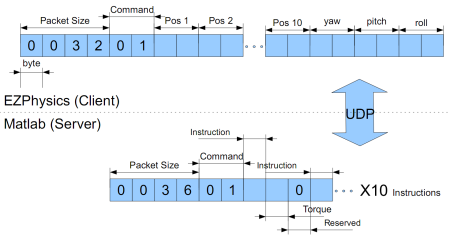
The information sent between the two applications is only 32 bytes client sending and 36 bytes receiving. We send from the client the joints rotational positions and the yaw,pitch and roll of the torso. And Matlab sends the instruction (CW, CCW, HOLD), the torque value (one byte resolution between 0 and MAX_TORQUE) and a third byte of information for future use:

To download this demo visit source forge (the source code available the isn’t updated yet):

https://sourceforge.net/projects/ezphysics/files/EZPhysics%20Matlab%20Module.zip/download

ODE’s servo simulation

October 30, 2010 by

In our project, we need to influence the robot’s movements by applying rotational force to robot’s motorized joints.  Applying Torque values to the joints requires calculations that are prone to errors, some of which are dependent on robot’s simulated environment. In addition, the physics engine would take some steps to update the velocity based on the force, which in the case of servos, is irrelevant since they work at supposedly constant speed (not necessarily consistent speed, as seen in previous post by Ricardo) .

However, the design of ODE was made thinking on the simulation of servos (and motors in general). Due to this, beyond the possibility to apply a force to a joint, it is also possible to set the joins parameters with desired speed and maximum applicable torque to achieve that speed. This allows us to create a very simple model that represents a real servo.

As the names suggest, desired speed is a constant that represents the required velocity  either positive or negative. The maximum torque is the absolute maximum force that the servo can apply to achieve the desired speed. For instance, with desired speed zero the engine will resist external forces up to maximum torque effectively simulating a PID servo attempting hold position.

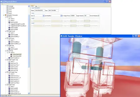
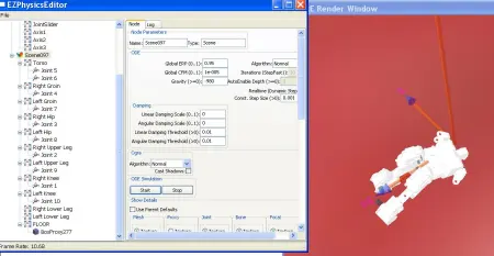
To take advantage of this feature EZPhysics Editor was updated to allow for the settings of this parameters by pressing a key, which allows for the rapid prototyping of the scale of forces needed to move the hinges:

We added a new option in the control node of EZPhysics to allow either the application of a force/torque to a joint or the application of a motor with fixed speed. The flag (ForceOrTorque —  not such a great choice of words) indicates wether that control node applies a torque or applies a simulated motor.

CM5 code to interface Roboard and Servos

October 30, 2010 by

The code to interface the Servos and the Roboard has already been explained on previouse post, so as brief explanation, this code colects the data from the servos, compose a pack with it and send it to the Roboard.
When the Roboard send a packet containing broadcast packets to the servos data, the CM5 will redirect the content to the servos.

Here is the first working version of the CM5 firmware.

See full article for the Code to Interface with the Servos

Read the rest of this entry »

Diving into Control Mechanics

October 30, 2010 by

A simple example that show the servos remotely controlled working as expected  (gravity is low):

CHR-6dm Attitude and Heading Reference System (IMU)

October 30, 2010 by

This Inertial Moment Unit (IMU) is a bunch of sensors  that are supposed to tell the robot’s brain the position and orientation of the robot. Typically solid state gyros, accelerometers and magnetometers are used. However, these sensors have varying degree of error, delay and accumulating delay and error. To deal with errors, the naive approach is to use a filter that smooths the signal but that approach creates delay. The textbook way of dealing with these limitations is to use a predictive algorithm that assumes that the measured object has body weight and inertia and in return provides a very low latency clean signal. Kalman Filter is the classic solution but more modern algorithms provide better results.

Instead of dealing with these problems, a recent development in IMU’s has spawned several small boards that integrate several sensors plus a small processor that does all the fancy math and sends out a low latency smooth signal in the form of a bit stream. All we lazy robot developers have to do is read the XYZ and yaw-pitch-roll data off the board’s serial connector.

To get the principal space position the IMU is once placed in  the head of our Jacobian1 robot.

The IMU that we are using is CHR-6dm Attitude and Heading Reference System.

” The CHR-6dm AHRS is a cost-effective
orientation sensor providing yaw, pitch, and
roll angle outputs at up to 300 Hz.  An
Extended Kalman Filter (EKF) combines data
from onboard accelerometers, rate gyros,
and magnetic sensors to produce yaw, pitch,
and roll angle estimates.
Communication with the CHR-6dm is
performed over a           L (3.3V) UART at 115200
Baud.  The AHRS can be configured to
transmit raw sensor in addition to angle estimates, and the transmission rate can be configured
in 1 Hz increments from 20 Hz to 300 Hz.  Alternatively, the CHR-6dm can operate in “silent
mode,” where data is transmitted only when specific requests are received over the UART.
Regardless of the transmission mode and rate, internal angle estimates are maintained at over
500 Hz to ensure long-term accuracy.
The CHR-6dm simplifies integration by providing a number of automatic calibration routines,
including rate gyro bias calibration, magnetometer hard and soft iron calibration, and
accelerometer “zeroing” to compensate for AHRS-platform misalignment.  All calibration routines
are triggered by sending simple commands over the serial interface.

The CHR-6dm AHRS is a cost-effective  orientation sensor providing yaw, pitch, and  roll angle outputs at up to 300 Hz.  An  Extended Kalman Filter (EKF) combines data  from onboard accelerometers, rate gyros,  and magnetic sensors to produce yaw, pitch,  and roll angle estimates.    Communication with the CHR-6dm is  performed over a           L (3.3V) UART at 115200  Baud.  The AHRS can be configured to  transmit raw sensor in addition to angle estimates, and the transmission rate can be configured  in 1 Hz increments from 20 Hz to 300 Hz.  Alternatively, the CHR-6dm can operate in “silent  mode,” where data is transmitted only when specific requests are received over the UART.   Regardless of the transmission mode and rate, internal angle estimates are maintained at over  500 Hz to ensure long-term accuracy.    The CHR-6dm simplifies integration by providing a number of automatic calibration routines,  including rate gyro bias calibration, magnetometer hard and soft iron calibration, and  accelerometer “zeroing” to compensate for AHRS-platform misalignment.  All calibration routines  are triggered by sending simple commands over the serial interface. …”

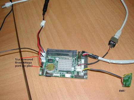
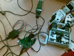
To test the IMU, we are using a RB110 Roboard and one of the first problems that we had, was that UART 3 and 4 were not found by Linux, so as temporary work around, we just disabled UART 0 and 1 in the BIOS and put the same IRQ interruption address of  0 and 1 , to 3 and 4.

To connect the IMU to the board, we have used the 5v from UART0 to supply the Vxx (see RB110 datasheet page 8 to 14) for the experience, once the power available on the Uart3 pins is Vxx.

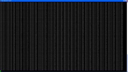
On our first test, with Roboard and the IMU, is a little code running in the Roboard that unpack the data from IMU and just print it, with 115200 Baud of speed in UART3.

Testing and evaluating Servos performance

October 27, 2010 by

(22-10-2010)

With the CM5 firmware ready, its now time to make a little program on the roboard, to test the servos.

This program will test the delay that the servos take moving between several angles, for example between 0º and 300º, or 0º to 100º, etc.

We will also run these tests on the  same servos, in several conditions, with different loads, different supply voltages, different maximum torques, and both at the same time.

We will also test the torques with different voltages .

The idea is to profile the servos as best we can so that they can accurately be emulated in EZPysics.

(27-10-2010)

At this point, we wrote a little program that sends the servos to a start point, and then to an end point, and repeats the process for 10 times.

During this process, the program saves to a file, every servomotor positions and make a timestamp with uSeconds precision, each time it receives a new packet from Roboard containing the servos data.

We reached the following results so far:

1) With 10 servos we get and average of 283 packets per second coming from the CM5

2) Some servos are slower than others.

3) around 1 second to go from 0 to 1023 which means 300º/sec at 12V in accordance with AX12 specs

4) the worst delay between any two servos was around 21º for completion of the 300º. This translates to around 7% error.

5) The old AX12 servos seem to be more problematic and some of the physical connectors seem to be faulty maybe due to so much messing around.

After this we just took the file from the roboard, using winscp, and imported it to Exel, elaborating a graphic, to easily visualize, the behaviour of the servos in time.

In the picture below you can see that some AX12 servos are faster than others. The servos are told to move from position 0 to position 1023 and then back. During the transition, the CM5 continuously captures the servo positions (at around 280 times per second) and sends those positions to the RoBoard, which in turn stores them in CSV file format which Excel then transforms into nice graphs.

The top graph shows the difference between the maximum and minimum values among the 10 servos sampled at 280/sec. The bottom graph shows the absolute positions of the fastest and slowest servo.

As you can see, the RoBoard waits for all the servos to reach 0 before sending them off to 1023, then waiting for all of them to reach that position and so on.

See the full article to view the C code running on the RoBoard Linux

Read the rest of this entry »

A Messy Mesh overflows the Mesh Masher (collision detection)

October 6, 2010 by

Upon implementing collision detection with GIMPACT (the package used by Bullet)  in ODE, our physics engine, the results were highly unsatisfying. It runs at sensibly the same speed has OPCODE (ODE original collision detection package) and it also crashes with a stack overflow if the complete bioloid is added to the collision detection scene.

When this problem was investigated it turn out that the problem afflicted ODEs sample bunnies also and not only our simulation.

However, upon following a topic found online it was  revealed that the cause of this crash was the meshes inside the meshes. Meaning the bunnies were inside each other and the collision detection algorithm behaves very poorly under these circumstances. The collision detection expects meshes that represent the colliding area of an object, meaning only the outer edges of it. For instance, this simulation has more bunnies and it does not overflow:

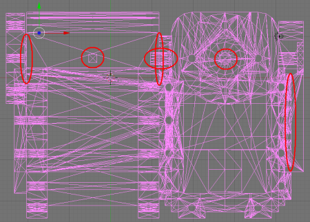
Returning to our model, we realize that the SolidWorks exported mesh is very messy. There is excessive detail and many interior triangles (the kind the collision detection algorithm does not expect). In the following image some problems are highlighted but many others are present in the image:

The solution path to this problem is a simple yet a hard one, the editing of all problematic vertexes to achieve a good behavior when inserted into ODE.

EZPhysics – adding mass properties interactively

October 6, 2010 by

EZPhysics is a to-be open source project focused on robot simulation using the ODE physics library. Given that ODE may be the best choice for this project’s goals and all the extra features included in EZPhysics it is now our main simulation environment.

This transition has been in progress for a while now and has started to give the initial results:

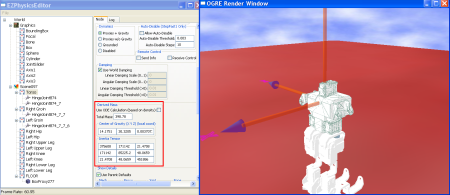
As a way to dive into the EZPhysics code, I added the possibility of interactively adding mass properties to ODE body entities. Original version was limited to calculating mass and inertial automatically from proxies and their mass density and shape.

By allowing the addition of mass property, it is now possible to export values from SolidWorks into the simulation. However, SolidWorks program exports peculiar aligned inertia matrix and center of mass which has been a source of trouble and odd bugs.. @$!

Problems with the communication, due to physical RS232 interface limitations

September 24, 2010 by
Our goal to have 1mbps communication between the CM5 and the Roboard, this is necessary to get as much as possible free processor time between packets.
The PC communications link on both the CM5 and CM510 is based on RS232 standard (12V).
The AVR processor on these boards has serial UART ports at 5V standard (TTL/CMOS). To do the step-up voltage conversion, CM5 uses the HIN232 chip and CM510 uses the MAX202C chip. Unfortunately these chips can only drive 125kbps and not 1mbps as we need.
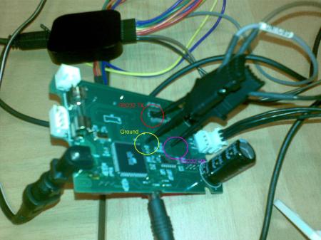
To analyze the RS232 communications we have used the Saleae Logic Analyzer, connected to the lines between the Atmega microcontroller and the RS232 Transceiver (HIN232). You can see the probes in the following picture.
Our Communication consists in a packet from CM5 to Roboard composed by
[0xFF] [0xFF] [Len] [ID1] [POSLsb] [POSMsb] [ID2] [POSLsb][POSMsb]…[IDn] [POSLsb] [POSMsb] [CRC]
In reply to this packet Roboard has to send another packet that is basicly a an emcapsulation of Servo Sync write packets inside a single packet, composed by
[0xFA] [0xFA] [PacketLenLsb] [PacketLenMsb] [Sync write Packet 1] [Sync write Packet 2] … [Sync write Packet N] [CRC]
and a Servo Sync write Packet Packet is composed by
[0xFF] [0xFF] [0xFE][Len][0x83][ServoStartAddress][NbytesToRight][ID1] [Data1] [Data2] […] [DataN] [ID2] [Data1] [Data2] […] [DataN]…[IDn] [Data1] [Data2] […] [DataN][CRC]

In this case we just have one servo broadcast packet to send, to set positions on servos.
Even though the chips are rated with 125Kbps limitation, we manage to get stable communication at 500Kbps but only in one direction : CM5 to PC. In the picture below you can see the sequence of bytes sent from the CM5 to the Roboard and perfectly captured.

In the picture below you can see that the sequence of bytes sent between the  PC and the CM5, data flowing both directions at 500kbps, one communication and reply goes well but the second is not received correctly.

Analyzing a the packet we can see the difference between the bytes that we want to send the CM5, and the bytes being actually sent on the wire.


If the CM5-Roboard speed becomes a bottleneck, we will replace the the CM5 and the CM510 IC components with a chip called TRSF3232E from Texas Instruments that has the exact same package and pinout but supports 1Mb/s speed, this change may also require changing the capacitors used as “voltage pumps” in accordance with TRSF3232E component datasheet.

Installing Linux on Roboard and FTDI tests

September 19, 2010 by

Installing ROBOARD with linux-image-2.6.29.1-vortex86dx

In the ROBOARD page we found what we need to do the installation following the regular Tutorial of installation of Debian Lenny. We also have in the drivers and the board RB100 manual and RB110 manual.

Everything went well until the installation blocks on the Ethernet devices search.

To solve it, the solution was setting the USB DEVICE on the BIOS, as “Force FDD”.

To Install the Debian on it, we need ethernet connection, which brougth us another problem, the roboard RB110, the one with the FTDI chip, had a problem of non recognized MAC ADDRESS by the bios, to solve this, we’ve used MAC_Tools given by roboard Tech help.

After a successful installation, we needed to install the FTDI drivers to control the chip, install GCC and G++, and editor, in this case, FTE and vim had to be installed using apt-get.

Installing a d2xx driver was simple, just need to follow the instructions on www.ftdichip.com, and it will recognize the chip and use the driver. We didn’t use the on-board chip but rather used an external device (USB2Dynamixel from Robotis) in order to connect the RoBoard to the CM5 Bioloid controller via its UART1.

CM5 UART -> RS232 level converting chip -> USB2Dynamixel -> USB -> RoBoard.

Installing the VCP (Virtual serial Communications Port) driver, was not so easy, the compilation had a lot of errors, found that there was a mismatch of kernel and lib symbolic links, and a lot of other problems, so we did not manage to get it working. The VCP driver for Linux was written by some guy on sourceforge and not formally endorsed by FTDI.

To solve this problem we decided to install ROBOARD with linux-image-2.6.34.1-vortex86dx, already released, it comes with the FTDI chip VCP drivers, which is automatically recognized on the system, and ready to use, even with hot plug.

A Little program have been made to test the ttyUSB port, based on a loop.

Example code:

#include <sys/time.h>
#include <sys/types.h>
#include <unistd.h>
#include <stdio.h>
#include <sys/types.h>
#include <sys/stat.h>
#include <fcntl.h>
#include <termios.h>
int main(void)
{
    fd_set Reading;
    int fdHandler;
    struct timeval timeout;
    char Data;
    struct termios termios_p;
    fdHandler = open(“/dev/ttyUSB0?,O_NONBLOCK|O_RDWR|O_NOCTTY);
    if(fdHandler==-1)
    {
        //shit hapened
        puts(“Error Opening”);
    }
    puts(“Port Open\n\rApply Settings”);
    termios_p.c_iflag=0/*IGNPAR | ICRNL*/;
    termios_p.c_oflag=0;
    termios_p.c_cflag= B500000/*|CRTSCTS*/|CREAD|CS8|CLOCAL;
    termios_p.c_lflag=0;
    termios_p.c_cc[VINTR]    = 0;     /* Ctrl-c */
    termios_p.c_cc[VQUIT]    = 0;     /* Ctrl-\ */
    termios_p.c_cc[VERASE]   = 0;     /* del */
    termios_p.c_cc[VKILL]    = 0;     /* @ */
    termios_p.c_cc[VEOF]     = 0;     /* Ctrl-d */
    termios_p.c_cc[VTIME]    = 0;     /* inter-character timer unused */
    termios_p.c_cc[VMIN]     = 0;     /* blocking read until 1 character arrives */
    termios_p.c_cc[VSWTC]    = 0;     /* ” */
    termios_p.c_cc[VSTART]   = 0;     /* Ctrl-q */
    termios_p.c_cc[VSTOP]    = 0;     /* Ctrl-s */
    termios_p.c_cc[VSUSP]    = 0;     /* Ctrl-z */
    termios_p.c_cc[VEOL]     = 0;     /* ” */
    termios_p.c_cc[VREPRINT] = 0;     /* Ctrl-r */
    termios_p.c_cc[VDISCARD] = 0;     /* Ctrl-u */
    termios_p.c_cc[VWERASE]  = 0;     /* Ctrl-w */
    termios_p.c_cc[VLNEXT]   = 0;     /* Ctrl-v */
    termios_p.c_cc[VEOL2]    = 0;     /* ” */
    tcflush(fdHandler, TCIFLUSH);
    if(tcsetattr(fdHandler,TCSANOW, &termios_p)==-1)
    {
        puts(“Error setting configurations”);
        return 0;
    }
    FD_ZERO(&Reading);
    while(1)
    {
        timeout.tv_sec  = 1;
        timeout.tv_usec = 0;
        FD_SET(fdHandler,&Reading);
        puts(“Send: A”);
        write(fdHandler,”A”,1);
        if(select(100,&Reading, NULL, NULL, &timeout)==-1)
        {
            puts(“Select Fail”);
        }
        if(FD_ISSET(fdHandler,&Reading))
        {
            puts(“Received: “);
            read(fdHandler,&Data,1);
            puts(&Data);
        }
    }
}
Code to html converted using CodeHTMLer

A Ragdoll in EZphysics (ODE)

September 19, 2010 by

The simulation parameters used with the PhysX based simulator have now ported into EZphysics with similar results:

The simulation is slower than with PhysX, however it will probably improve with parameter tuning and/or simpler collision meshs.